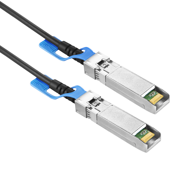
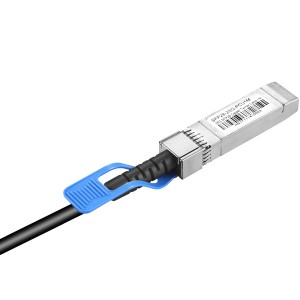
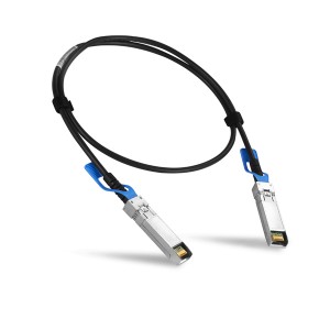
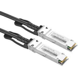
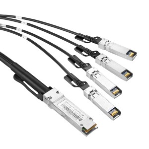
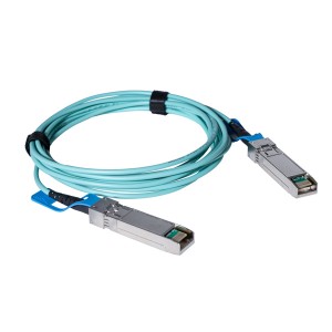
25G SFP28 Direct Attach Cable (DAC) JHA-SFP28-25G-PCU
General Description
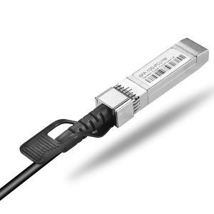
SFP28 Direct Attach Cables are compliant with SFF-8432 and SFF-8402 specifications. Various choices of wire gauge are available from 30 to 26 AWG with various choices of cable length (up to 5m).
The SFP28 passive cable assemblies are high performance, cost effective I/O solutions for 25G Ethernet. SFP28 copper cables allow hardware manufactures to achieve high port density, configurability and utilization at a very low cost and reduced power budget.
Features
◊ Up to 25.78125 Gbps data rate
◊ Up to 5 meter transmission
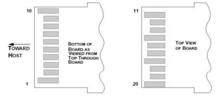
◊ Hot-pluggable SFP 20PIN footprint
◊ Improved Pluggable Form Factor(IPF) compliant for enhanced EMI/EMC performance
◊ Compatible to SFP28 MSA
◊ Compatible to SFF-8402 and SFF-8432
◊ Temperature Range: 0~ 70 °C
◊ RoHS Compatible
Benefits
◊ Cost-effective copper solution
◊ Lowest total system power solution
◊ Lowest total system EMI solution
◊ Optimized design for Signal Integrity
Applications
◊ 25G Ethernet
High Speed Characteristics
|
Parameter |
Symbol |
Min |
Typical |
Max |
Unit |
Note |
||
|
Differential Impedance |
RIN,P-P |
90 |
100 |
110 |
Ώ |
|||
|
Insertion loss |
SDD21 |
8 |
22.48 |
dB |
At 12.8906 GHz |
|||
|
Differential Return Loss |
SDD11 |
12.45 |
See 1 |
dB |
At 0.05 to 4.1 GHz |
|||
|
SDD22 |
3.12 |
See 2 |
dB |
At 4.1 to 19 GHz |
||||
|
Common-mode to |
SCC11 |
dB |
||||||
|
common-mode |
2 |
At 0.2 to 19 GHz |
||||||
|
SCC22 |
||||||||
|
output return loss |
||||||||
|
Differential to common-mode |
SCD11 |
12 |
See 3 |
dB |
At 0.01 to 12.89 GHz |
|||
|
return loss |
SCD22 |
10.58 |
See 4 |
At 12.89 to 19 GHz |
||||
|
10 |
At 0.01 to 12.89 GHz |
|||||||
|
Differential to common Mode |
SCD21-IL |
See 5 |
dB |
At 12.89 to 15.7 GHz |
||||
|
Conversion Loss |
||||||||
|
6.3 |
At 15.7 to 19 GHz |
|||||||
|
Channel Operating Margin |
COM |
3 |
dB |
|||||
Pin Descriptions
SFP28 Pin Function Definition
| Pin |
Logic |
Symbol |
Name/Description |
Notes |
||
|
1 |
VeeT |
Transmitter Ground |
||||
|
2 |
LV-TTL-O |
TX_Fault |
N/A |
1 |
||
|
3 |
LV-TTL-I |
TX_DIS |
Transmitter Disable |
2 |
||
|
4 |
LV-TTL-I/O |
SDA |
Tow Wire Serial Data |
|||
|
5 |
LV-TTL-I |
SCL |
Tow Wire Serial Clock |
|||
|
6 |
MOD_DEF0 |
Module present, connect to VeeT |
||||
|
7 |
LV-TTL-I |
RS0 |
N/A |
1 |
||
|
8 |
LV-TTL-O |
LOS |
LOS of Signal |
2 |
||
|
9 |
LV-TTL-I |
RS1 |
N/A |
1 |
||
|
10 |
VeeR |
Reciever Ground |
||||
|
11 |
VeeR |
Reciever Ground |
||||
|
12 |
CML-O |
RD- |
Reciever Data Inverted |
|||
|
13 |
CML-O |
RD+ |
Reciever Data Non-Inverted |
|||
|
14 |
VeeR |
Reciever Ground |
||||
|
15 |
VccR |
Reciever Supply 3.3V |
||||
|
16 |
VccT |
Transmitter Supply 3.3V |
||||
|
17 |
VeeT |
Transmitter Ground |
||||
|
18 |
CML-I |
TD+ |
Transmitter Data Non-Inverted |
|||
|
19 |
CML_I |
TD- |
Transmitter Data Inverted |
|||
|
20 |
VeeT |
Transmitter Ground |
||||
|
1. |
Signals not supported in SFP+ Copper pulled-downto VeeT with 30K ohms resistor | |||||
|
2. |
Passive cable assemblies do not support | LOS and TX_DIS | ||||
Mechanical Specifications
The connector is compatible with the SFF-8432 specification.
| Length (m) | Cable AWG |
|
1 |
30 |
|
2 |
30 |
|
3 |
30/26 |
|
4 |
26 |
|
5 |
26 |
Regulatory Compliance
|
Feature |
Test Method | Performance |
| Electrostatic Discharge (ESD) to the Electrical Pins | MIL-STD-883C Method 3015.7 | Class 1(>2000 Volts) |
| Electromagnetic Interference(EMI) | FCC Class B | Compliant with Standards |
| CENELEC EN55022 Class B | ||
| CISPR22 ITE Class B | ||
| RF Immunity(RFI) | IEC61000-4-3 | Typically Show no Measurable Effect from a 10V/m Field Swept from 80 to 1000MHz |
| RoHS Compliance | RoHS Directive 2011/65/EU and it’s Amendment Directives 6/6 | RoHS 6/6 compliant |

